
Pcb Board
PCB Board Creation Project
Timeline
10/27:
Received 3 PCB design files and generated the G-code using MakeraCam. Each file represented a different layer of the board: the copper traces, drill holes, and outline cut.
10/29:
Attempted to use the CNC machine to cut the board for the first time. We ran into a major issue: the measurements for the copper board size were incorrect in the G-code, causing the CNC cuts to be misplaced on the copper board. The scaling and origin were off, so the traces didn’t line up properly.
10/30:
Fixed the scaling issue by ensuring all units matched between MakeraCam and the CNC software (using millimeters). We re-exported the G-code and after all the troubleshooting, the board cut correctly and aligned perfectly.
MakeraCam Workflow:
MakeraCam Workflow
- Open MakeraCam.
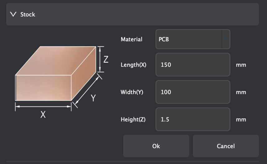
- Open project 3-axis (set Length: 150mm, Width: 100mm, Height: 1.5mm)
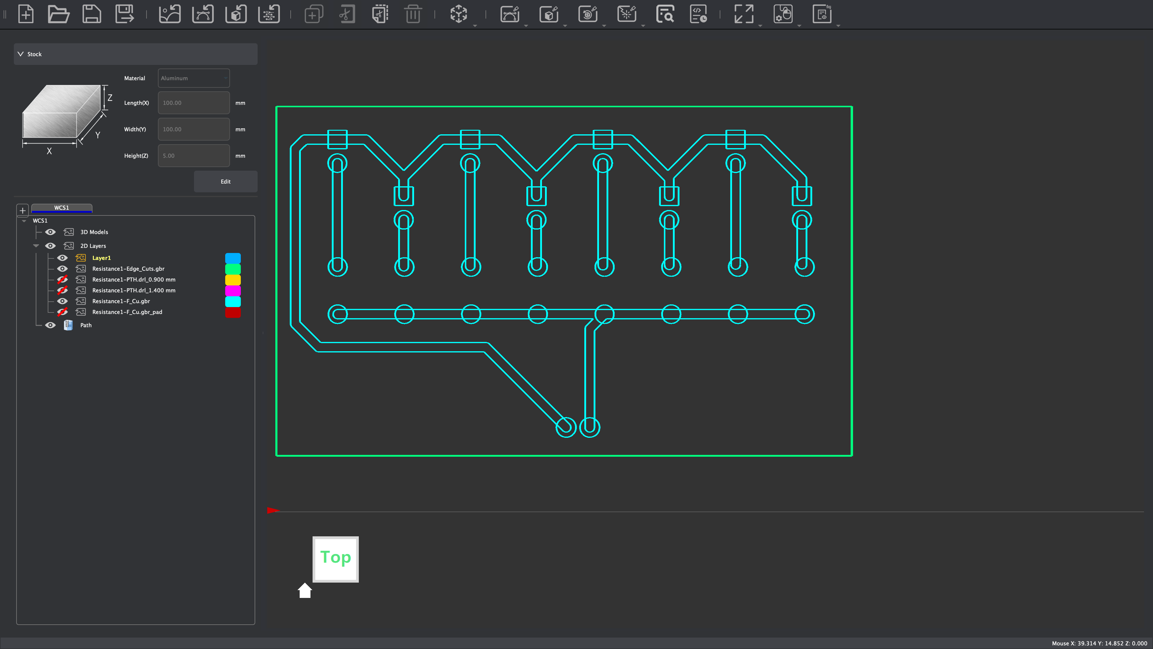
- Import PCB files:
File - Import PCB - Edge Cuts.gbr(board outline)File - Import PCB - F.Cu(top layer copper)File - Import PCB - Resistance1-PTH.drl(drill file for CNC holes)
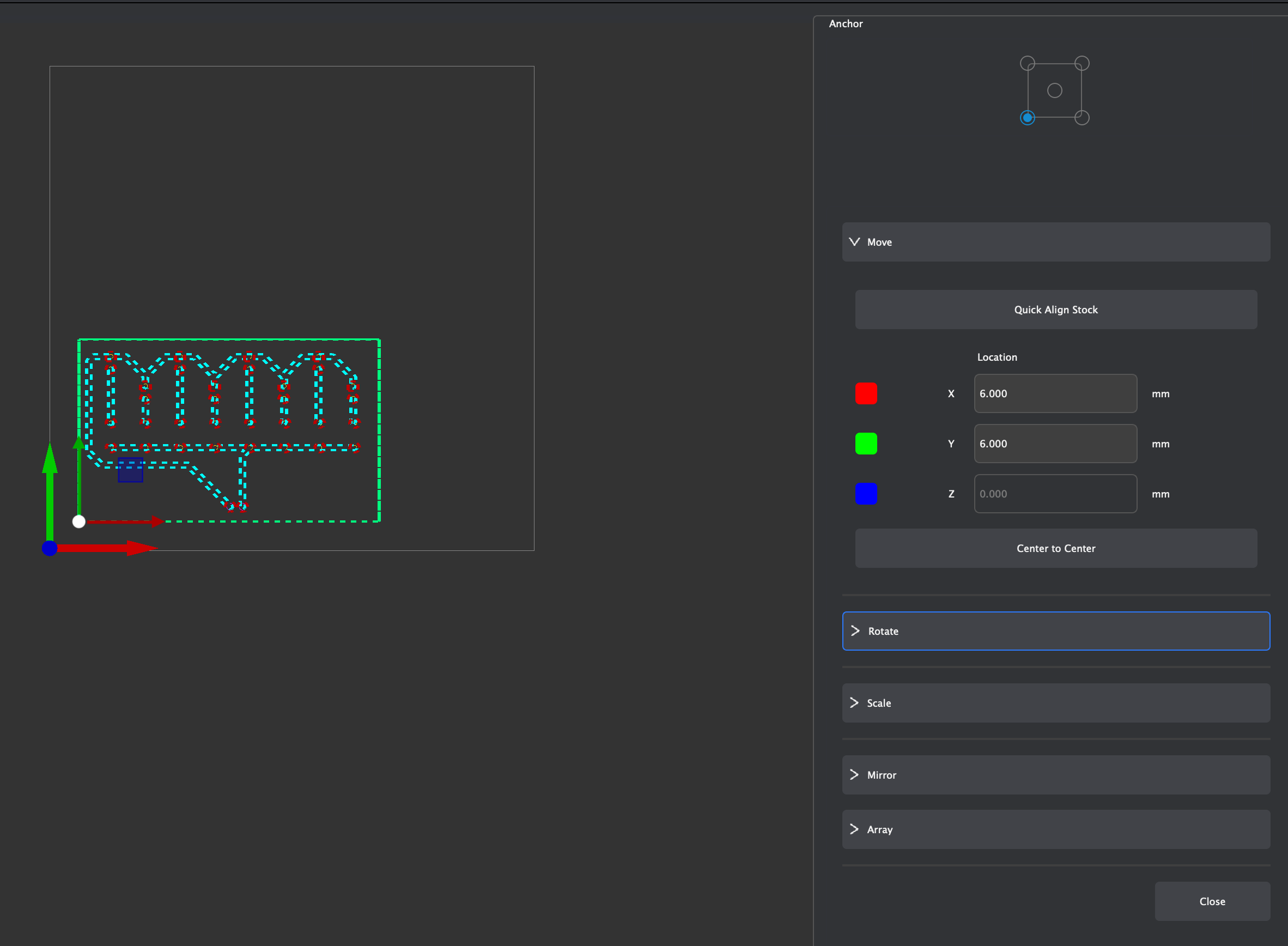
- Select the board and press M, set the anchor to the bottom-left corner, and move board to
(6, 6)Note: Dotted object = selected, solid = not selected
- Deselect the top line:
- Go to top line, hold Shift, and deselect it
- Block the bottom three files.
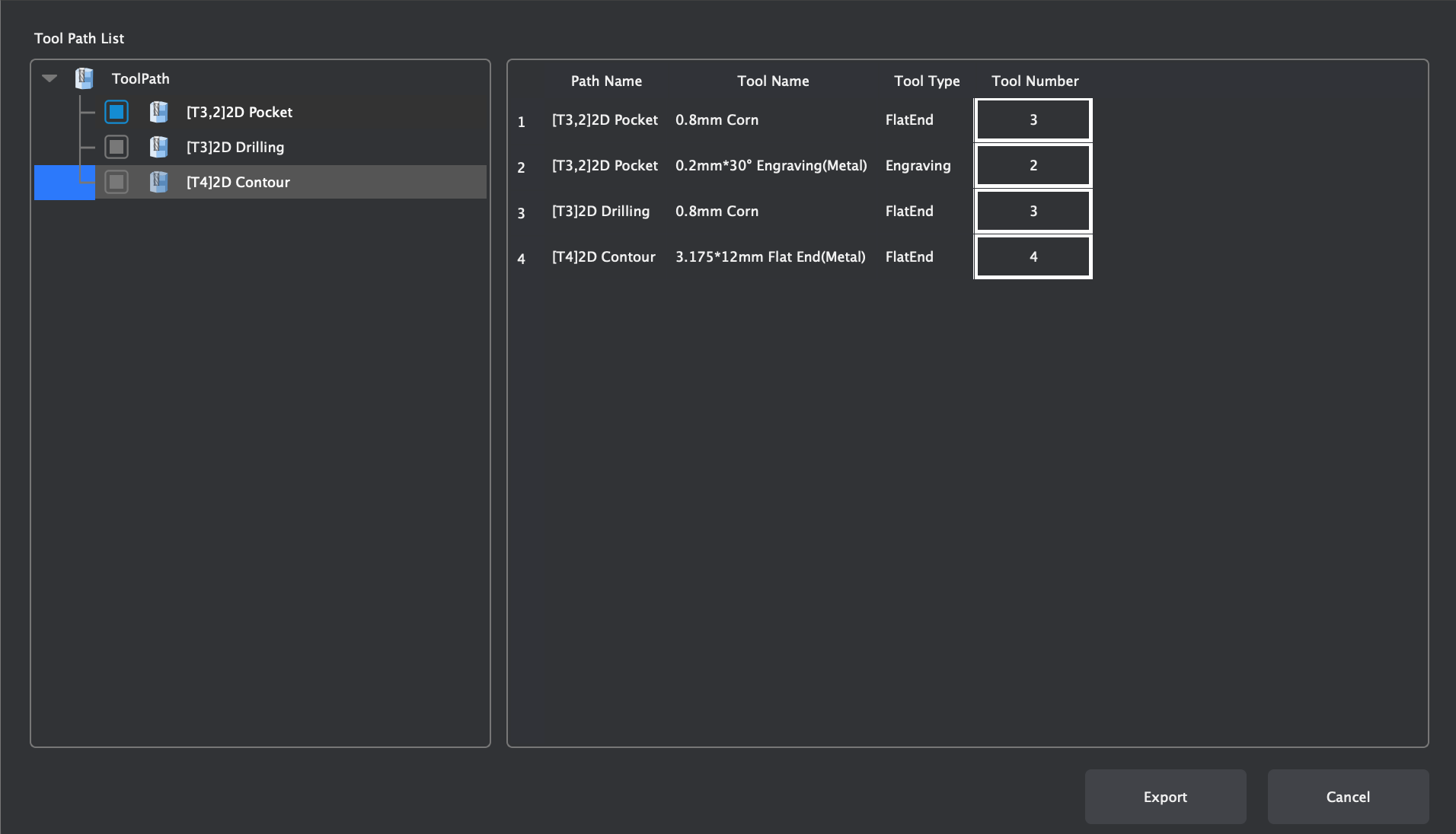
- Add 2D Pocket toolpath:
- Set end depth to
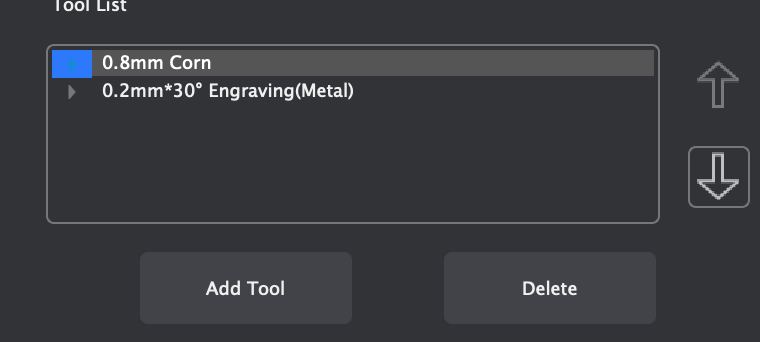
0.05mm - Add tools:
0.8mm Corn0.2mm × 30 Engraving (Metal)
- Select tool - click Calculate

- Set end depth to
- Block everything except the drill files.
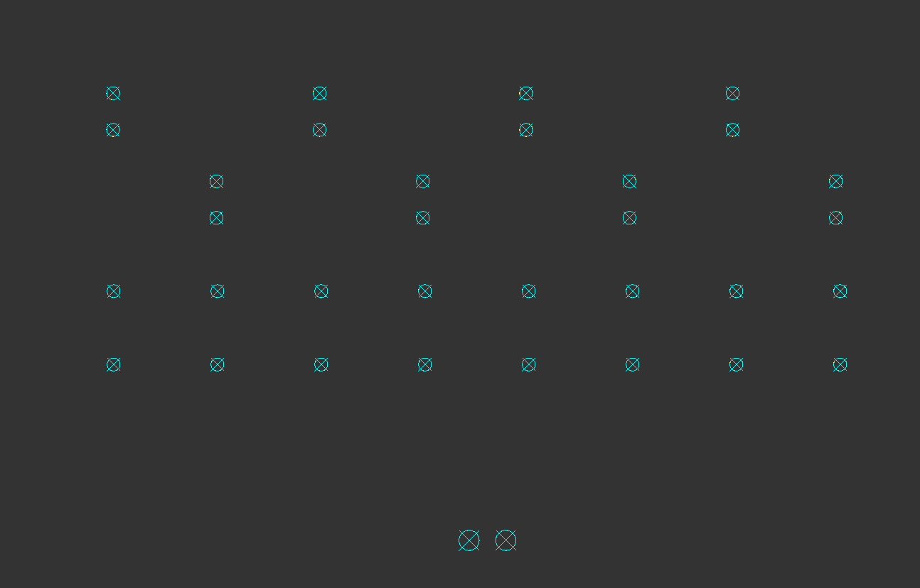
- 2D Drilling:
- Select everything
- Set drill tip end depth to
1.7mm - Use only
0.8mm Corntool - click Calculate
- Block everything except the resistance edge cuts:
- Deselect top line, select bottom line
- 2D Contour:
- End depth
1.7mm - Tool:
0.8mm Corn - Strategy: Position = Outside
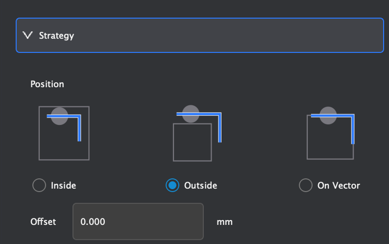
- End depth
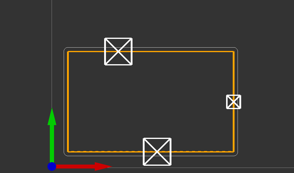
- Add tabs:
- Go to
Tabs - Custom - Add- click on the selected box (use 3 tabs)Note: Offset tabs slightly — do not place them directly across from each other, or the board may break
- Go to
- Click Preview at the top to review the toolpaths.
Download MakeraCam Workflow (PDF)
CNC Cutting Workflow:
- First put the copper in the corner
- Tighten the bolts near the inside of the copper to hold it in place
- Tighten the bracket to help hold the copper in place(make sure the small side is the one holding the copper down)
- Then go to carver controller software
- Download your gcode file
- Press open gcode in the bottom left and select and upload the gcode file you are using
- After file uploaded hit run gcode in bottom left(to the right of open gcode)
- Once you are in config and run
- Auto vacuum: on
- Select scan margin
- Select auto leveling
- Click run (ensure the voltage is above 3.6 before running)
Download CNC Cutting Workflow (PDF)
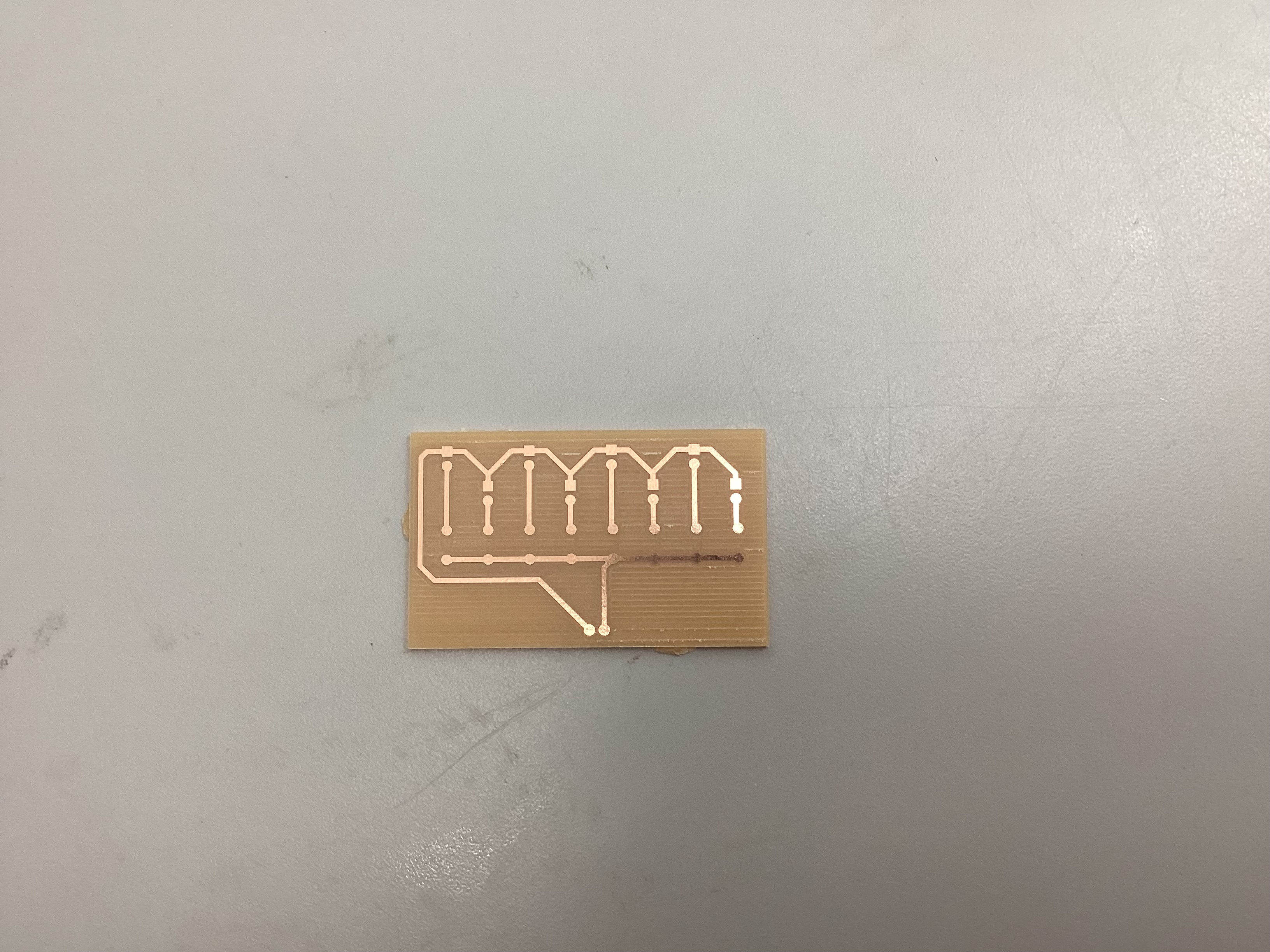
Image of Final PCB Board:
Gcode File (.nc):
Download Gcode File (.nc)
PCB Milling Files:
Download Milling Files (.zip)
Reflection:
This project taught me how important it is to check scaling, units, and alignment before running the CNC. After fixing those issues, we were able to successfully cut the PCB board, and it matched our schematic perfectly.