Cnc Mountain Topo
Creating a Topographic Mountain Model: Terrain2STL to Makera Carvera ATC
This post details the end-to-end workflow for transforming real-world terrain data into a physical 3D model using a combination of Terrain2STL, Vectric Aspire 12.5, and the Makera Carvera ATC CNC machine.
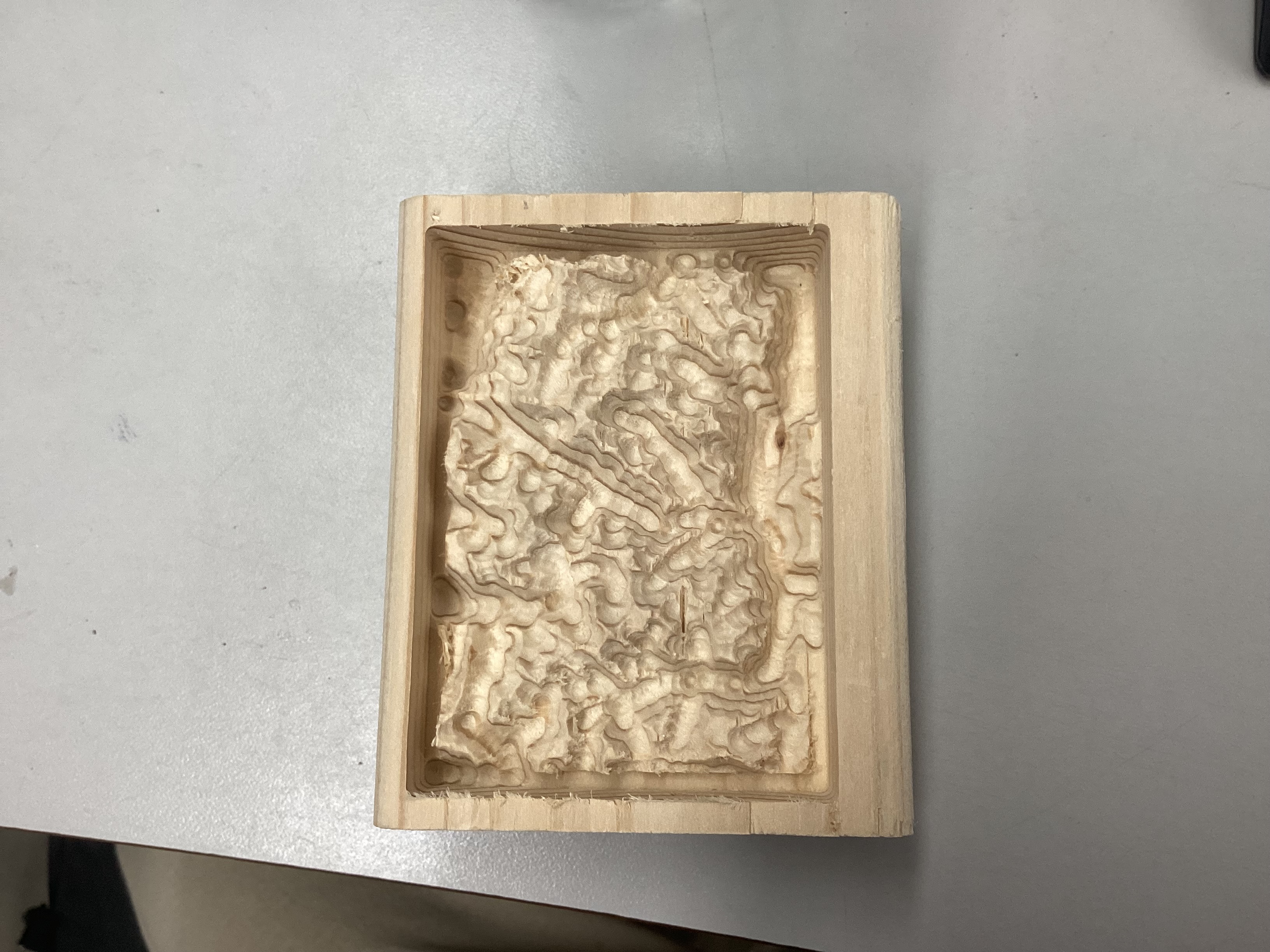
Final Topography Image
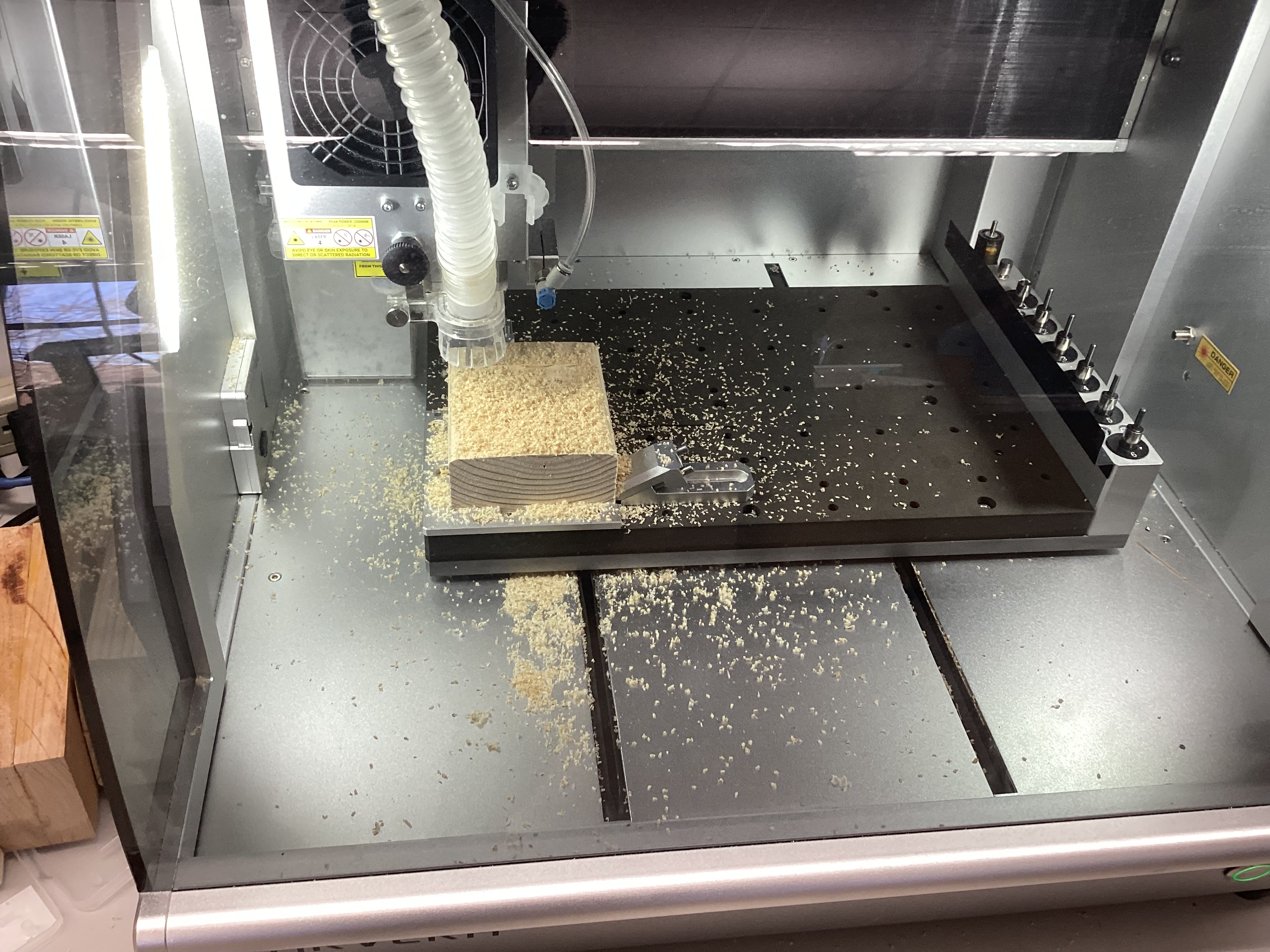
Topography Cutting Process
Workflow – Topographic Maps Creation
-
Access and Location: Navigate to https://jthatch.com/Terrain2STL/. Click Center to View to place the initial red selection box.
-
Define the Model Area: Pan and drag the red box to precisely cover the mountainous area you wish to model.
- Adjust Model Settings: Crucial adjustments for a mountain model:
- Vertical Scaling (Z-Scale): This is essential. I used a value of 2.5 to exaggerate the mountains and valleys, making the relief stand out clearly on a smaller physical model. (The default of 1 often results in too-subtle relief.)
- Base Height (mm): Set to a small value, like 1.0 mm, to ensure the model has a solid base for CNC carving.
- Generate and Download: Click Generate Model. The website will process the data and download a
.ZIPfile containing the.stlfile.
My Terrain:
- Create New File & Define Stock:
- Set Job Type to Single Sided.
- Set Job Size (X, Y) and Thickness (Z) to match your physical stock material (e.g., X=5 inches, Y=7 inches, Z=1 inch).
- Z Zero Position: Set to Material Surface (essential for the Carvera).
- XY Datum Position: Set to Bottom Left.
- Import & Orient 3D Model:
- Go to the Modeling tab and click Import a Component or 3D Model. Select your
.stlfile. - In the 3D Orientation window, set Initial Orientation to Top.
- Model Size: Uncheck the lock to adjust the Z-size independently. Set the Z height to a value less than or equal to your stock thickness (e.g., Z=0.95 inches for 1-inch stock).
- Click Apply, Center Model, and then Position and Import.
- Go to the Modeling tab and click Import a Component or 3D Model. Select your
- Component Properties: In the Component Tree, right-click the imported component and select Properties.
- Set Shape Height to the final desired height (e.g., 1.0 inch).
- Set Base Height to 0.0 to push the lowest part of the relief right down to the bottom of the modeled component area. This maximizes the model’s presence within the stock material.
- Center the Component: Switch to the 2D View (Design Tab), select the model, and use the Center tool to align it with the stock.
- Create Boundary Vector: Use the Draw Rectangle tool to create a vector that outlines the final dimensions of your piece. This vector will be used for both machining limits and the final profile cut.
-
3D Roughing Pass: * Tool: 1/8” Flute End Mill (Tool #1 for the Carvera ATC). * Machining Limit Boundary: Select the Model Boundary (the vector you created). * Machining Allowance: Set to 0.024” to leave material for the finer finishing bit. * Strategy: Z Level.
-
3D Finishing Pass: * Tool: 1/8” Ball Nose (Tool #6 for the Carvera ATC). (A smaller tool would add more detail, but this balances detail and time for the initial run.) * Strategy: Raster, set at a 0-degree angle to run along the grain of the wood.
-
2D Profile Toolpath: * Tool: 1/8” Flute End Mill (Tool #1). * Cut Depth: Set to 0.5 inch (or a desired depth to create a small base). * Machine Vectors: Select On the line. * Note: If you intend to cut all the way through the stock, ensure you use the proper Cut Depth and add Tabs (I opted for a partial cut and used a bandsaw for final separation).
-
Preview All Toolpaths: Click the Preview all Toolpaths button. Critically examine the simulation. Does the relief look right? Are there any missed areas or unexpected cuts?
- Save G-Code: * Click Save Toolpaths. * Select all three toolpaths (3D Rough, 3D Finish, 2D Profile). * Choose the Carvera ATC (mm) (*cnc) post-processor. This combines the cuts into a single file for automated tool changes on the Carvera.
Workflow – CNC Milling Proccess
- Connect Carvera: Open the Carvera Controller software on the desktop. In the top toolbar, click the status button (typically “N/A disconnected”) and select the appropriate COM port.
- Home the Machine: Click the menu in the top right corner and select “Switch to display manual control interface” followed by the Home button.
- Load Files: In the bottom left corner, click the folder icon to open your .cnc (G-code) file exported from Aspire.
- Preview Toolpaths: Go to the top right menu and click “Switch to display file preview interface” to verify the toolpaths look correct before cutting.
- Configure Run: Click Config and run. Ensure “auto leveling” is OFF
- Verify Anchor & Run: Ensure your work coordinate is set to Anchor 1 (to avoid the machine starting in the wrong spot) and click Run.
Project Summary
What I Learned
The most critical takeaway is the relationship between the digital design and the physical material constraints.
- Z-Scale is Key: Ensuring the right Z-axis in Terrain2STL is crucial for achieving clear topographic visibility on a small-scale CNC model and making sure that the mountain cuts with the right dimensions.
- Aspire’s Base Height: Understanding the Base Height properties in Aspire is crucial for correctly positioning the 3D component relative to the stock surface, preventing material from being cut off or wasted.
-
- Aspire’s Toolpaths: Understanding which toolpath to use for the model is crucial, so you are able to use the correct techqnieus with the precise tool to accurately cut your topography.
Future Plans
My next project would be to create a larger version of this mountain, adding extra design elements like an LED strip at the base to create a light up version of my mountain.
Project Files
You can find the necessary project files below for review and replication:
TOPO_MOUNTAIN_PROJECT.crv3d- The native Aspire project file.TOPO_MOUNTAIN_TOOLPATHS.cnc- The Makera Carvera G-Code file.STL_Mountain_Export.stl- The raw 3D model exported from Terrain2STL.